What kind of meshing mechanism does the rubber timing belt use to achieve non-slip synchronous transmission?
2025-04-30
The geometric interlocking of tooth profile and tooth groove locks the sliding space
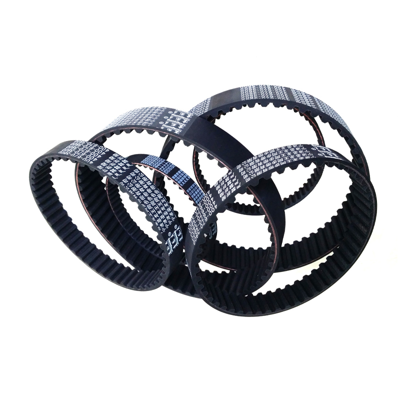
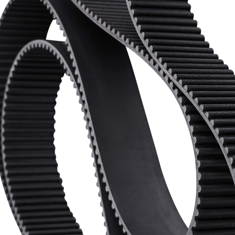
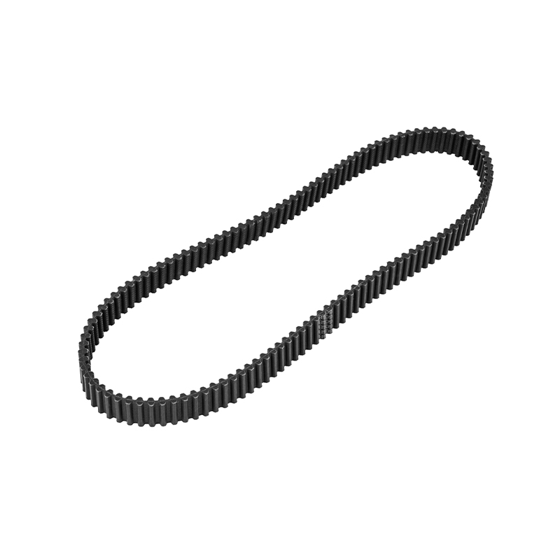
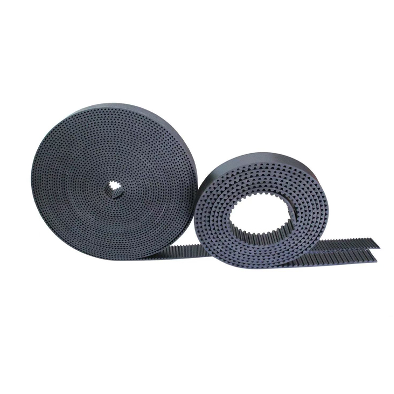
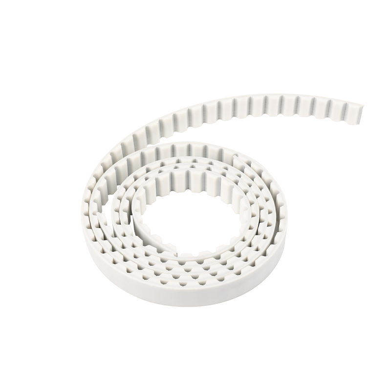
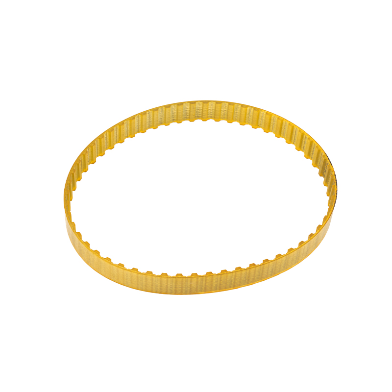
The trapezoidal or arc tooth profile on the inner circumference of the Rubber Timing Belt and the tooth groove of the pulley form a geometric complementary structure. The two are injection molded by precision molds, and the pitch tolerance is strictly controlled within ±0.05mm. When the belt is tensioned, the tooth top forms a three-point rigid contact with both sides of the tooth groove. This surface contact interlocking relationship completely blocks the relative sliding path of the traditional friction transmission. Taking the application of automobile engines as an example, when the crankshaft rotates at a high speed of 5000rpm, the tooth profile interlocking can withstand a tangential force of more than 200N/mm, and still ensure that the linear speed error between the pulley and the belt is less than 0.3%, which is equivalent to a cumulative transmission error of no more than 1.5° phase deviation per 100,000 kilometers.
Balancing mechanism of dynamic meshing stiffness and deformation compensation
The belt base material adopts a composite formula of chloroprene rubber and hydrogenated nitrile rubber, and the Shore hardness is controlled in the range of 65-75HA, which not only ensures the rigid support of the tooth structure, but also gives it a 3%-5% elastic strain space. Under the impact of engine explosion pressure, the rubber matrix absorbs instantaneous impact energy through local deformation to avoid stress concentration caused by tooth rigidity collision; in steady-state operation, the modulus recovery characteristics of the glass fiber reinforced layer (tensile modulus> 8GPa) can quickly reset the deformation and maintain the precise meshing of the tooth and pulley. This combination of rigidity and flexibility allows the timing belt to maintain a tooth matching accuracy of 0.1mm under extreme temperature differences from -40℃ to 120℃.
Failure mode control under multi-physics field coupling
The synchronization of the transmission system not only depends on tooth meshing, but also needs to overcome the dual challenges of material aging and dynamic load. Under long-term alternating stress, the rubber matrix will undergo segment breakage and molecular cross-linking degradation, resulting in a tooth height wear rate of 0.02mm/10,000 kilometers; and the glass fiber layer may experience microcrack expansion during bending fatigue, causing the belt length elongation to exceed the critical threshold of 0.5%. To suppress such failures, Hyundai Rubber Timing Belt adopts a sandwich structure design: the outer wear-resistant layer (added with silicon carbide particles) stabilizes the friction coefficient of the tooth surface in the range of 0.3-0.4, the middle skeleton layer disperses the stress through the 45° bias-woven glass fiber cord, and the inner buffer layer absorbs vibration energy through the foaming process. This layered protection system allows the belt life to exceed the threshold of 100,000 kilometers, and some high-end products can even reach a maintenance-free cycle of 180,000 kilometers.
Digital verification of synchronous transmission accuracy
In modern manufacturing, the tooth profile accuracy of Rubber Timing Belt is double-detected by laser 3D scanning and CT tomography, and products with tooth profile error ≤0.02mm can enter the assembly line. In the engine bench test, a high-precision encoder (resolution 0.001°) is used to monitor the phase difference between the crankshaft and the camshaft in real time, and a high-speed camera (frame rate > 5000fps) is used to capture the dynamic deformation of the belt tooth profile. Data shows that after a 100,000-kilometer endurance test, the phase deviation of a high-quality timing belt can still be controlled within ±0.5°, which is equivalent to a timing error of no more than 0.28% of the crankshaft angle. This accuracy is close to the lower performance limit of gear transmission.


 English
 中文简体
中文简体